
The Propex heaters were designed to be safe and reliable heat sources for your vehicle. Being mounted in a non-stationary vehicle presents its own challenges as the units are subject to vibration and exposure to all types of environments. Because of this, Propex designers err on the side of caution and create distinct operating parameters for the heating units. If the heater's electronic protection system senses the unit is outside safe operating parameters, it will show a fault code and shut down for inspection.
This article is for the four flash code. If your thermostat continually flashes four times between pauses, this is for you.
Below is from the thermostat handbook that comes with your Propex unit.
Number of Flashes - 4
Fault - Combustion air fault
Remedy - Check combustion air flue and exhaust flue for blockages. Possible blockage in combustion air inlet/outlet duct. Inspect duct for blockage/ damage. Inspect the inlet pipe on the heater (closest to the back) for signs of damage.
Here is a video of what the four flash code will look like on your thermostat. Please note that the cadence will be the same regardless if you have an analog or digital thermostat.
Step One
The first thing to do is reset your unit from the thermostat. If the four flash code come back, proceed to step two.
Step Two
Confirm both the intake and exhaust pipes on the bottom of the unit are each 1 meter in length and that they are the original Propex supplied pipes. For optimal performance, these pipes should not be shortened, lengthened, or switched out with anything other than stock replacements.
Please Note: We understand there is old literature still floating around stating these pipes can be shortened or lengthened. However, we do NOT recommend it. We have heard of units running fine for years with modified pipes until they don't. Leaving you without a functioning heater.
If you need to replace your pipes, we sell new ones on our website here.
Step Three
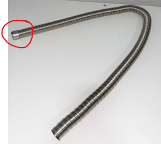
Confirm that the stock end caps are located at the end of both the intake and exhaust pipes. Though these seem small and insignificant, they do play a role in the restriction of air going into and coming out of the heater, and they are important to its function.
Step Four
Confirm there are no cuts, knicks, pinches, bends, or any other visible damage to either the intake or the combustion pipes on the bottom of the unit. Make sure to inspect them closely. Just because you don't see one at first glance does not mean it's not hiding on the other side of the pipe mounted to your vehicle.
Step Five
Confirm the routing of your intake and exhaust pipes are correct.
Check to make sure your intake and exhaust are far enough apart that the intake pipe is not sucking in the exhaust fumes from the heater.
Make sure that the exhaust pipe is at a gradual slope exiting out the side or back of your vehicle. Exhaust rises, and you do not want the exhaust to settle under your vehicle. You also want to avoid a long vertical drop with the exhaust pipe. We recommend no more than a 6-inch vertical drop at any point in the pipe. Having more than a 6-inch drop will cause a chimney effect. The fan will not be powerful enough to expel all the fumes in the exhaust pipe, causing them to back up into the unit and ultimately causing a four-flash code.
Step Six
Check your regulator! A failing or incorrectly calibrated regulator causes around 80% of all four-flash codes. Please do not overlook this step.
Confirm you have a high-quality two-stage regulator. Single-stage regulators or low-quality regulators have inconsistent or fluctuating pressure, and this will cause the unit to throw a code.
Confirm your regulator is set to 11.5" water column.
Please note: Most off-the-shelf regulators will say they are set to a specific water column, but with any mass-produced product, there is room for variation. For example, the regulators we purchase are said to be set to 11.5" water column, but when we test them, they are anywhere between 10"-15" inches. We manually re-calibrate every single one before we put them on the shelf to sell. The only way to confirm your regulator's pressure is to either purchase our pre-calibrated regulator or check yours with a manometer.
Video of how to test your regulator.
Step Seven
Clear your intake and combustion pipes. During the life of your unit, the internals can become dirty or dusty and will need to be cleaned. The fresh air pipe is constantly sucking in outside fresh air, which is often full of tiny dust or pollen particles. These contaminants can dirty the airflow sensor and cause a four-flash code. We have also seen bugs, rodents, spiderwebs, and other pests that like to crawl up the intake and exhaust pipe when the unit is not in use. Don't worry; the access points from the intake and exhaust pipes do not lead to your cabin, so there is no way for any of these things to make their way inside your cabin.
The goal here is to clean out whatever is inside the unit. You will need compressed air and a vacuum to perform the next steps (you may also need a partner).
With your vacuum held over the exhaust pipe outlet, blow compressed air into the fresh air intake pipe. This will cause a vacuum inside the unit and, hopefully, clear out anything that is inside. After 30 seconds, switch the vacuum to the intake pipe and blow compressed air into the exhaust pipe. We like to go back and forth a few times just to make sure everything is out. If you want, you can leave one end open and only use compressed air. This will allow you to see what is coming out the other end. Please be sure to keep your face away from the other pipe.
Here is a video of how to clean out your heater.
Step Eight
In-cabin air cleanout. When your heater runs, it will cycle your cabin air to keep the space nice and warm. If the air being drawn into the unit from the cabin is dirty, most likely dust bunnies or pet hair, these contaminants can cause the heater to run poorly. We recommend giving the unit a quick clean-out, as shown at the end of the video below.
Here is a video of how to clean out your heater.
Step Nine
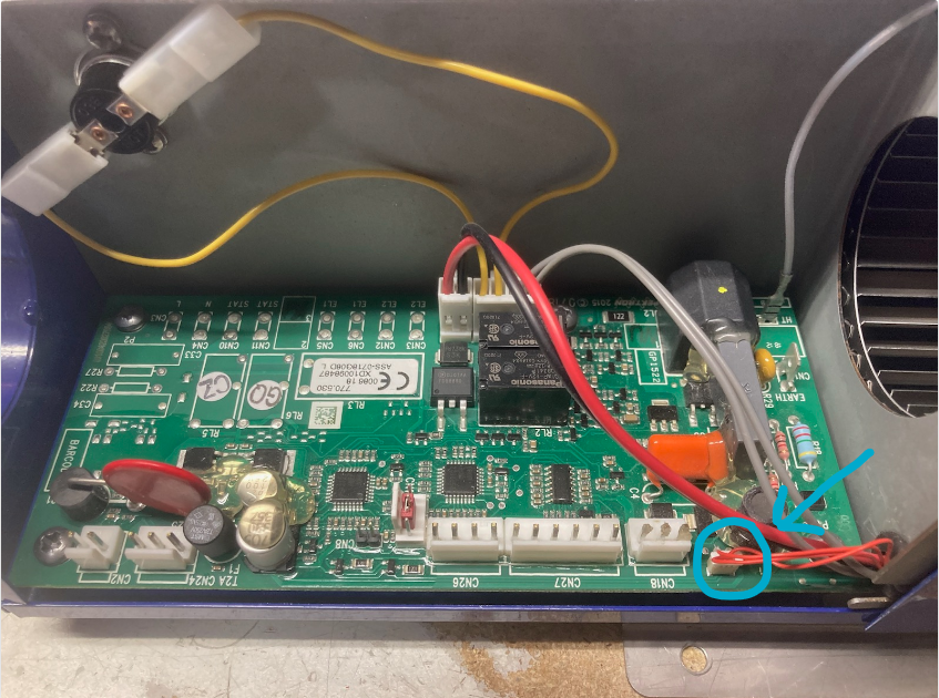
Confirm that your air flow sensor harness connected to the circuit board is plugged in and undamaged. It doesn't happen often, but we have seen this connection become loose and become inadvertently unplugged.
Step Ten
If the above steps do not fix your four flash code, you will need to send the unit in for servicing. Either your airflow sensor is clogged to the point of failure, or you have an issue with the circuit board itself.
This repair is NOT intended to be done at home! Please DO NOT attempt to open the Propex to fix your air flow sensor. It will need to be replaced by a member of our service department. There is also no field test for the PCB. We will need to diagnose the PCB in-house. Attempting any kind of repair on your own will damage the heater, and it will not work properly after the case is open.